Most camper electrical systems are designed backwards. The buyer picks a battery size that sounds generous, adds a solar panel that fits the roof, and then discovers in the first hot week that the air conditioning, the induction hob and the fridge cannot all run at once. The builds that work start at the other end: a load schedule, then an energy balance, then a battery, then the charging sources that keep that battery alive.
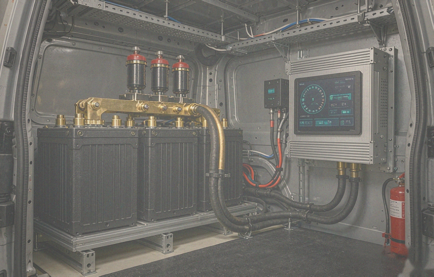
This article walks through a 10 kWh 24V off-grid RV system built into a converted medium-duty ambulance — a vehicle type that is becoming a serious alternative to a factory camper because the body, the wiring and the alternator are already commercial grade. The numbers below are the ones a pack engineer and an installer argue about: how much current the inverter actually pulls, how long a 900 W array takes to refill the bank, and what one hour of driving is worth in kilowatt-hours.
Why 24 V Is the Middle Ground
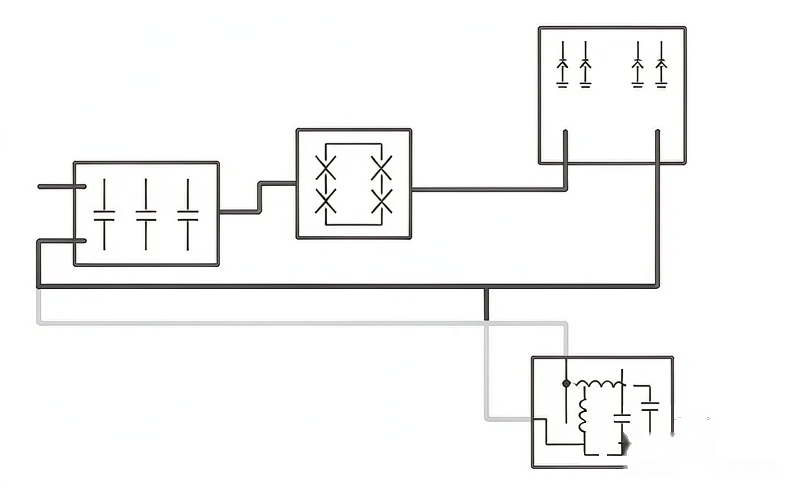
A 12 V system stays cheap and simple up to roughly a 2 kW inverter. Above that, the DC current becomes the design problem: a 3 kW load pulls 234 A at 12.8 V and starts demanding cable and terminals that belong in a truck workshop. A 48 V system solves the current problem but pulls the whole build into a different component class — 48 V chargers, 48 V inverters, 48 V DC-DC — which is the right answer for a 30 kWh coach and overkill for a 10 kWh camper.
Twenty-four volts sits in the gap. A 5 kVA inverter draws about 195 A at 25.6 V, which is manageable with 70 to 95 mm² cable, and most of the equipment a camper needs is either natively 24 V or available in a 24 V variant. The reference bank here is 8 LiFePO4 cells in series: 25.6 V nominal, 29.2 V at full charge, 400 Ah, which is 10.2 kWh.
| Bus voltage | Current for 4 kW | Typical cable | Sweet spot |
|---|
| 12 V (12.8 V nominal) | 313 A | 120 mm² and up | Up to about 2 kW of inverter |
| 24 V (25.6 V nominal) | 156 A | 50 to 70 mm² | 5 to 10 kWh, 3 to 5 kVA inverter |
| 48 V (51.2 V nominal) | 78 A | 25 to 35 mm² | 20 kWh and above, 5 kW and up |
Start With a Load Schedule, Not a Battery
A load schedule is the least glamorous document in the build and the only one that prevents an expensive mistake. List every AC and DC load, its real average draw, how many hours a day it runs, and multiply. Average draw matters more than nameplate power: an induction hob rated at 1.8 kW runs for twenty minutes, not four hours, while a fridge draws 55 W continuously and quietly adds up to more energy over a day.
| Load | Average draw | Hours per day | Energy per day |
|---|
| Mini-split cooling | 650 W | 3.0 | 1,950 Wh |
| Compressor fridge | 55 W | 24.0 | 1,320 Wh |
| Induction hob | 1,800 W | 0.4 | 720 Wh |
| Satellite internet terminal | 45 W | 6.0 | 270 Wh |
| Lights, pumps, roof fan | 30 W | 8.0 | 240 Wh |
| Laptops, phones, camera | 60 W | 4.0 | 240 Wh |
| Diesel heater fan and pump | 10 W | 6.0 | 60 Wh |
| Total |
|
| 4,800 Wh |
That is 4.8 kWh a day, and it is the number that makes the battery decision. A 10.2 kWh bank at a 90 percent usable window holds 9.2 kWh, which is almost exactly two days with no sun, no driving and no shore power. If the plan is "camp barefoot for a couple of days even when it is cloudy", the bank is correctly sized. If the plan is a week in the desert with air conditioning, it is not, and no amount of solar will fix a bank that is two sizes too small.
Sizing the Inverter and the DC Side
A 5 kVA inverter is not chosen for average load, it is chosen for the worst simultaneous load: mini-split at 650 W, induction at 1,800 W and the fridge compressor kicking in at 300 W surge. That is about 2.8 kW, comfortably inside 5 kVA with headroom for a kettle or a power tool.
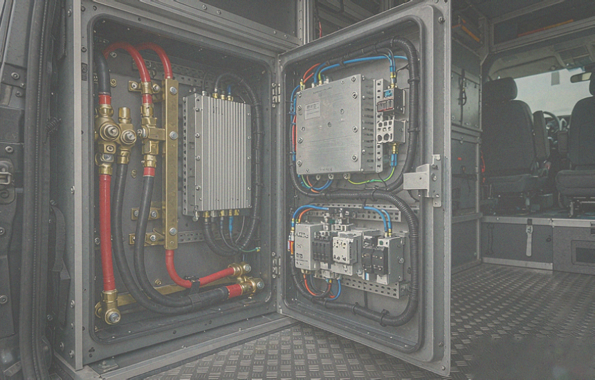
The DC side is where installers get hurt. At 25.6 V, 5 kVA is 195 A before efficiency losses and closer to 212 A at 92 percent efficiency. Cable, fuse and terminal ratings all have to be selected for that number, not for the inverter's marketing name. Undersized DC cabling does not fail politely: it heats at the terminals, derates the inverter and, in the worst case, becomes the ignition point of the build.
| DC current at 25.6 V | Typical cable, short run | Fuse or breaker |
|---|
| 78 A (2 kW) | 25 to 35 mm² | 100 A |
| 156 A (4 kW) | 50 mm² | 200 A |
| 212 A (5 kVA at 92 percent) | 70 to 95 mm² | 250 A |
| 234 A (6 kVA) | 95 to 120 mm² | 300 A |
Treat that table as a starting point for runs under two metres, then verify against the local wiring code and the actual insulation temperature rating. Long runs, bundled cables inside a closed cabinet and high ambient temperatures all push the cross-section up.
Solar: 900 W Into a 60 A Controller
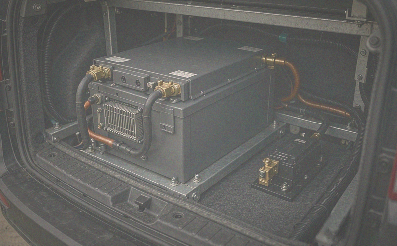
A 900 W array on a 25.6 V bank needs roughly 31 A of charge current at 29.2 V, so a controller rated at 60 A leaves the door open for a second array later up to about 1.7 kW of output capacity. Oversizing the controller is one of the cheapest forms of future-proofing in an RV build, because panels are easy to add and controllers are usually buried behind a panel.
Expect less than the array's nameplate. Three and a half good peak-sun hours at 80 percent system efficiency gives about 2.5 kWh a day, which covers half the daily load in the schedule above. In winter, at a northern latitude, expect a third of that: a 900 W array is a summer tool, and the alternator is the winter one.
| Source | Rate | Daily input | Covers |
|---|
| Solar, 900 W array | 900 W peak, about 31 A at 29.2 V | About 2.5 kWh in summer | Half of the 4.8 kWh daily load |
| Alternator through a 100 A buck-boost | About 2.5 kW at 25.6 V | About 2.3 kWh per hour of driving | Two hours driving refills a day of load |
| Shore power charger | 16 A at 230 V, 3.68 kW available | Full recharge in about four hours | Unlimited while hooked up |
Alternator Charging: The Fastest Source on the Vehicle
A commercial ambulance arrives with a heavy-duty alternator — in this case a 320 A unit — and that is the single most valuable charging asset in the build. The constraint is not the alternator's output, it is the charging device between it and the lithium bank. A 100 A buck-boost converter limits charge current to 100 A, which is about 2.5 kW at 25.6 V, and that number is deliberate: pulling the full alternator capacity into a 400 Ah bank would exceed the recommended charge rate and cook the alternator at idle.
Two engineering details make the difference between a setup that lasts and one that eats alternators. First, the converter has to follow a lithium charge profile with a proper absorption and float stage, not a fixed alternator voltage. Second, the alternator has to be able to survive long idling sessions at high output; if the plan is to charge at idle rather than while driving, a second alternator or a larger-case unit is cheaper than a replacement every two years.
Keeping the 12 V Chassis System Separate
The house bank runs at 25.6 V and the vehicle runs at 12 V, so the two never touch directly. A 24 V to 12 V DC-DC converter feeds the 12 V devices — lights, fans, radio, USB — straight from the house bank, which is more efficient than running a separate 12 V battery for them. The chassis battery keeps its own charging path so it is always ready to crank, and a voltage-sensing disconnect sits between the two worlds so a week of domestic loads can never leave the vehicle unable to start.
This is also the reason the original vehicle wiring can stay largely intact. Converting an ambulance or a commercial van means inheriting a loom that was designed for a working vehicle: lights, sirens, a PA system, a rear heater. Keeping that loom and feeding it from a 12 V converter preserves functionality that would cost thousands to rebuild, and it keeps the conversion reversible.
Heating and Cooling Decide the Load
Roof-top air conditioners are the default in factory campers and they are the reason so many of them cannot run off battery. A mini-split is roughly twice as efficient for the same cooling, draws around 650 W average in this build, and can also heat in mild weather. A diesel-fired heater handles cold nights on a few watts of electrical draw, because the energy comes from fuel rather than the battery.
The combination matters more than either unit. With a mini-split and a diesel heater, the daily load stays near 4.8 kWh and a 10 kWh bank is genuinely useful. With a rooftop unit pulling 1.5 to 2 kW, the same bank lasts a single afternoon — and the build silently becomes a generator-powered camper with extra steps.
Monitoring Is Not Optional
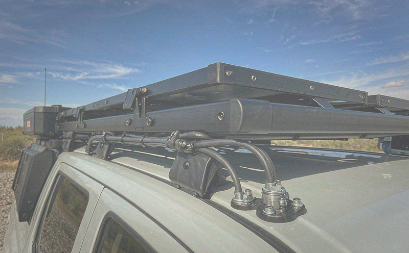
With a single shunt at the battery negative you get state of charge, current in and out, and consumed amp-hours — the three numbers that tell you whether the system is working. Add a busbar with monitored fuses and each circuit's draw becomes visible, which turns "the fridge seems to be running a lot" into a measurement.
Remote access changes how the vehicle is used. A system that reports state of charge, solar yield and charger status to a phone means you know before you go to bed whether tomorrow needs a two-hour drive or whether the array already covered the day. On a vehicle that spends weeks off grid, that information is worth more than another 100 Ah of battery.

The Build in One Table
| Item | Спецификация | Why this size |
|---|
| House bank | 25.6 V 400 Ah LiFePO4, 10.2 kWh, 8S | Two days of 4.8 kWh load at 90 percent usable |
| Inverter charger | 5 kVA, 24 V | 2.8 kW simultaneous worst case plus headroom |
| Solar array | 900 W, 60 A MPPT | About 31 A actual; controller allows growth to 1.7 kW |
| Alternator charging | 100 A buck-boost from a 320 A alternator | 2.5 kW while driving without overloading the bank |
| 24 V to 12 V | DC-DC converter, 30 A class | Feeds the original vehicle loom from the house bank |
| Measurement | Shunt rated well above 212 A, monitored distribution busbar | SOC accuracy and per-circuit visibility |
| Chassis protection | Voltage-sensing disconnect on the starter battery | Domestic loads can never strand the vehicle |
Five Things to Get Right Before You Drill
• Weight and balance. A 10 kWh LiFePO4 bank is around 80 to 100 kg depending on enclosure and BMS, and it belongs low and between the axles, not in a rear overhang.
• Ventilation. Inverter, MPPT and DC-DC all shed heat; a sealed cabinet with no airflow derates everything inside it and shortens component life.
• Fire separation. Lithium packs and fuel-fired heaters or fuel lines do not share a compartment without a physical barrier and a plan.
• Low-temperature charging. LiFePO4 must not be charged below 0 degrees Celsius. Either the BMS blocks charging until cells warm, or a heater pad keeps the enclosure above freezing.
• Serviceability. Every fuse, shunt and busbar connection should be reachable without dismantling the interior, because the first fault will find the one component you buried.
Sourcing the Bank
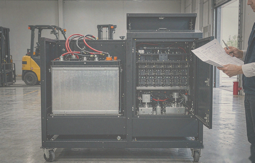
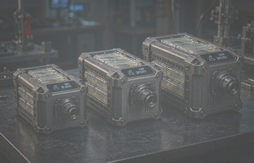
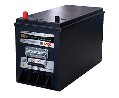
The battery is the one component in this build that cannot be improvised from a hardware store, and it is where a conversion either becomes reliable or becomes a monthly project. UFOPOWER is a professional lithium battery manufacturer producing 12 V, 24 V and 48 V LiFePO4 packs for RV, marine and off-grid applications, with in-house BMS design, welded busbars, temperature-sensed charge protection and CAN or RS485 communication for integration with the rest of the system.
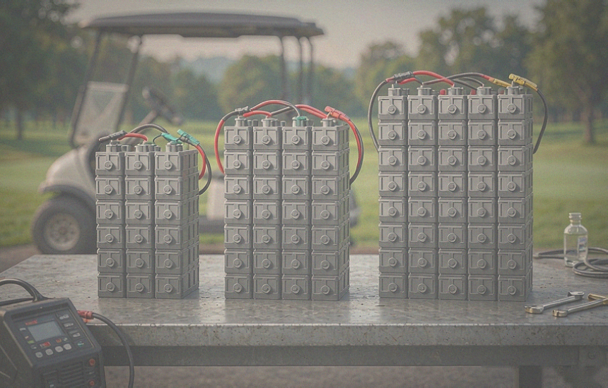
For a 10 kWh build the practical choice is a factory-assembled 25.6 V 400 Ah pack with a serial number and a test record, rather than four separate 100 Ah batteries wired by hand. Fewer connections means fewer failure points, one BMS sees all the cells, and OEM or ODM customization covers the enclosure dimensions, terminal layout and communication protocol that a vehicle conversion always ends up needing.
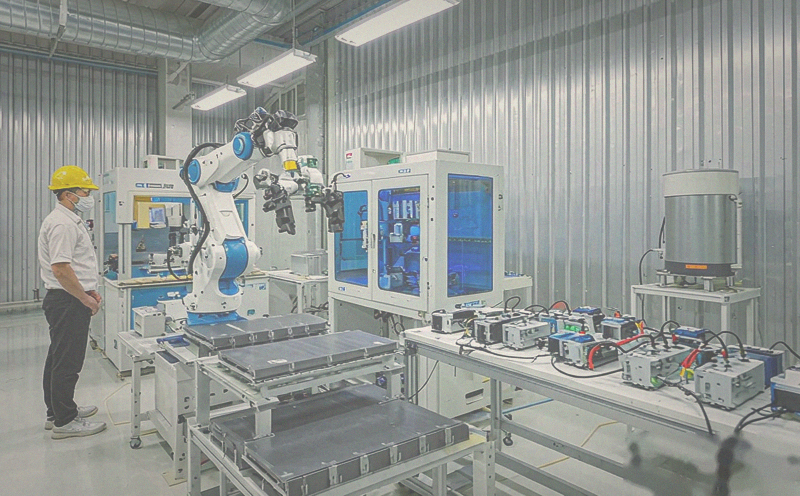
Send UFOPOWER your load schedule and the voltage you have settled on, and the reply comes back as a pack specification — capacity, continuous and peak current, BMS limits, enclosure and communication — instead of a catalogue page you have to interpret yourself.


 EN
 AR
 DE
 ES
 FR
 JP
 KO
 PT
 RU
 Главная >
 Nov 12, 2026





 в WhatsApp