A converted bus is not a camper with a bigger fridge. It is a house on wheels that expects to run a microwave, a compressor fridge, air conditioning and a coffee machine without asking anyone's permission. That expectation sets the battery, and the battery sets everything else: the inverter, the cable, the fuse, the chargers, and how long you can stay parked before someone has to start an engine.
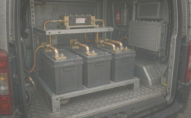
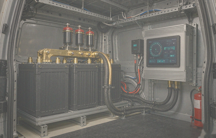
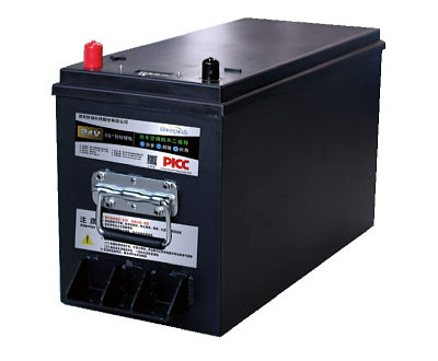
The system described here is a 9.2 kWh usable lithium reserve built from three 12.8 V 300 Ah LiFePO4 batteries — 900 Ah and 11.5 kWh stored — feeding a 5 kW inverter, with four independent ways to put energy back. The interesting engineering is not the kilowatt-hours. It is the 420 A that flows when the inverter is working hard, and the coordination problem created by having a solar controller, an alternator, a generator and a shore inlet all trying to charge the same bank.
What 9.2 kWh Actually Buys You
Stored energy and usable energy are different numbers. Three 12.8 V 300 Ah batteries store 11.52 kWh at nominal voltage; at a 80 percent depth of discharge the usable reserve is about 9.2 kWh. That is the number to plan with, because the last 20 percent is the BMS protecting the cells, not a resource you can spend.
| Quantity | Ценность | How it is derived |
|---|
| Installed capacity | 900 Ah at 12.8 V | 3 x 300 Ah batteries in parallel |
| Stored energy | 11.5 kWh | 900 Ah x 12.8 V |
| Usable reserve | 9.2 kWh | 80 percent depth of discharge |
| Baseline daily load | About 3 kWh | Fridge, lights, pumps, electronics, cooking |
| With air conditioning | About 9 kWh | Adding 1.5 kW for four hours |
So the honest answer to "how long can I stay?" is three days at baseline and roughly one day with the air conditioning running. That is not a defect in the bank; it is what air conditioning costs. A 1.5 kW cooling load for four hours is 6 kWh, which is two thirds of the entire reserve. Owners who understand this number stop blaming the batteries and start planning around the compressor.
Three Batteries, Not Nine
900 Ah could be assembled from nine 100 Ah batteries or three 300 Ah units. The three-unit build wins on almost every count: two-thirds fewer interconnects, one BMS view instead of three, balanced internal impedance, and a single point of failure per unit rather than nine chances to leave a terminal loose. On a vehicle that will vibrate for a decade, connection count is reliability.
Parallel strings still need care. All three batteries must be the same model, the same age and the same state of charge when installed, and the main positive and negative cables should come from opposite ends of the busbar so that current does not favour the nearest unit. Without that detail, the closest battery works hardest and ages first, and the bank's usable capacity starts shrinking from one end.
The 5 kW Inverter Problem at 12 V
This is where a 12 V architecture shows its limit. A 5 kW inverter at 12.8 V draws 391 A before losses and roughly 420 A at 93 percent efficiency. That is not a cable you buy at an auto parts store. It is 120 to 150 mm² copper, a 500 A class fuse, crimped lugs torqued to spec, and a run measured in centimetres rather than metres.
| Inverter load | DC current at 12.8 V | Cable | Fuse | Practical note |
|---|
| 2 kW | 168 A | 35 to 50 mm² | 200 A | Short runs, well crimped |
| 3 kW | 252 A | 70 mm² | 300 A | Keep under 1.5 m total |
| 5 kW continuous | 420 A | 120 to 150 mm² | 500 A | Battery and inverter in the same compartment |
| 10 kW surge, seconds | 840 A | As above | Fuse must tolerate inrush | Check BMS peak rating before assuming it is fine |
The BMS matters as much as the cable. A 900 Ah bank can supply 420 A comfortably at 0.47C, but the protection electronics inside each battery must be rated for the surge, and the inverter's inrush at switch-on has to be handled without tripping. On large 12 V systems, a pre-charge circuit or a BMS with a pre-charge output is not optional.
Four Chargers, One Bank
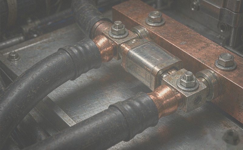
The recharge strategy is what makes a 9 kWh reserve practical, because no single source can refill it quickly. Solar is silent and slow, the alternator is fast but only while driving, the generator is fast but loud, and shore power is free but only where there is a hook-up. Each has a different charge rate and a different job.
| Source | Rate | Energy per hour | When it works |
|---|
| Solar, 3 x 360 W panels | About 79 A at 13.6 V | Up to 1.1 kWh at peak | Daylight, best in summer and at altitude |
| Alternator while driving | Limited by combiner and cable | Highest of the four | Only when the engine runs |
| Generator through the inverter charger | Up to 220 A | About 3 kW | Anytime, at the cost of noise and fuel |
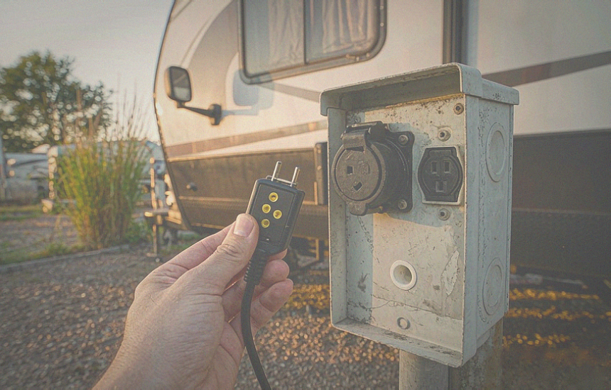
| Shore power, 110 V inlet | Whatever the charger is set to | Full recharge overnight | Only when hooked up |
The solar controller is sized just above the array: 1,080 W of panels into a unit rated 85 A, which at 13.6 V is about 1.16 kW of charge capacity. That small margin is deliberate headroom — panels rarely deliver nameplate, and the controller runs cooler and lasts longer when it is not pinned at its limit. Do not oversize an array far beyond the controller, because clipped energy is money spent on glass.
The generator is the heavy lifter: 220 A through the inverter's charger function is roughly 3 kW, which refills the usable reserve in about three hours of running. That is the number that decides whether a generator is worth its weight, and on a bus where air conditioning exists, it usually is.
Making Four Chargers Agree
Multiple charge sources on one bank create a control problem that is invisible until it causes damage. Each device has its own idea of absorption voltage and float voltage, and each one measures voltage at its own terminals, which is not the same as voltage at the battery when 220 A is flowing through a cable. The result is a charger that thinks the bank is full because it is reading its own output, while the battery is still 15 percent short.
• Set every charger to the same absorption and float targets, taken from the battery datasheet rather than from each device's default.
• Compensate for cable drop: either use remote voltage sensing at the battery, or raise the charger's target by the measured loss at full current.
• Accept that sources do not need to be coordinated in time — only in voltage. A solar controller and a generator charger can work simultaneously as long as both stop at the same point.
• Use a battery combiner or DC-DC charger between the alternator and the lithium bank; the alternator's fixed regulator is not a lithium charge profile.
• Keep one device as the reference for state of charge and let the rest be followers.
Cold Weather Is the Real Constraint
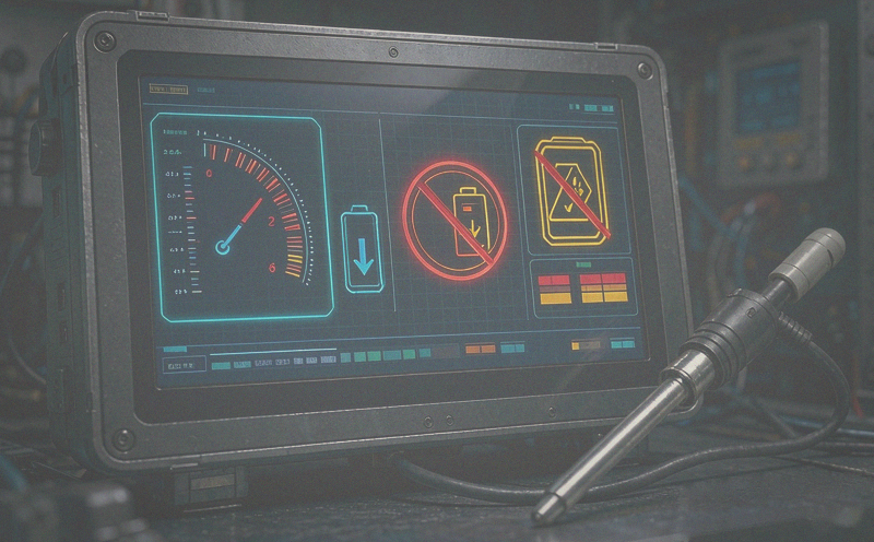
LiFePO4 can discharge well below freezing but must not be charged below 0 degrees Celsius, because lithium plates onto the anode and permanently removes capacity. In a bus that is used in winter, this is not a theoretical concern: the solar controller will happily try to charge at sunrise on a minus-five morning, and the alternator will try the moment the engine starts.
| Condition | Разряд | Charge | System response |
|---|
| Above 10 degrees C | Full rating | Normal | No action |
| 0 to 10 degrees C | Reduced capacity | Reduced current preferred | Watch temperature, limit charge rate |
| Below 0 degrees C | Allowed, with derating | Prohibited | BMS or charge-inhibit blocks every source, alarm sounds |
The practical solution used in this build is a temperature-sensed inhibit that not only stops charging but tells the operator why, with an audible alarm. The driver then starts the engine to warm the cabin, waits until the battery compartment is above freezing, and charging resumes normally. That is a human-in-the-loop design, and on a vehicle used in winter it is more reliable than a heater that nobody monitors.
Protection Layers, Not One Fuse
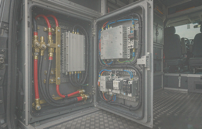
A 900 Ah bank stores enough energy to weld a wrench to a terminal. Protection is layered, and each layer answers a different failure. At the battery there is a main fuse sized for the cable, not for the load. At each circuit there is a device that disconnects on low voltage so a forgotten light cannot flatten the reserve. The DC distribution has individually fused outputs so a short in one branch does not take down the rest. And the BMS has the final say, disconnecting the pack if a cell goes out of range.
The undervoltage disconnects deserve their own note. In a bus there may be three or four of them — one for the inverter, one for the 12 V distribution, one for a small always-on circuit — and they are the difference between a flat reserve and a dead reserve. Set their thresholds above the BMS cutoff, so the loads drop off in an orderly way before the battery protects itself.
Retrofitting Is the Hard Part
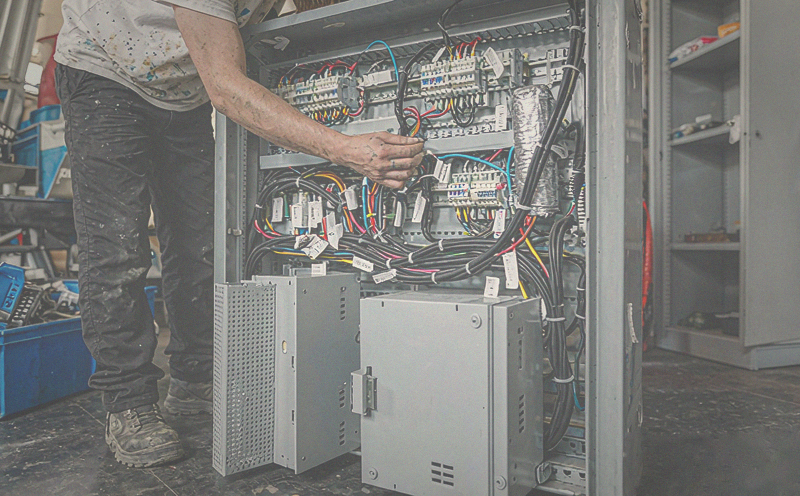
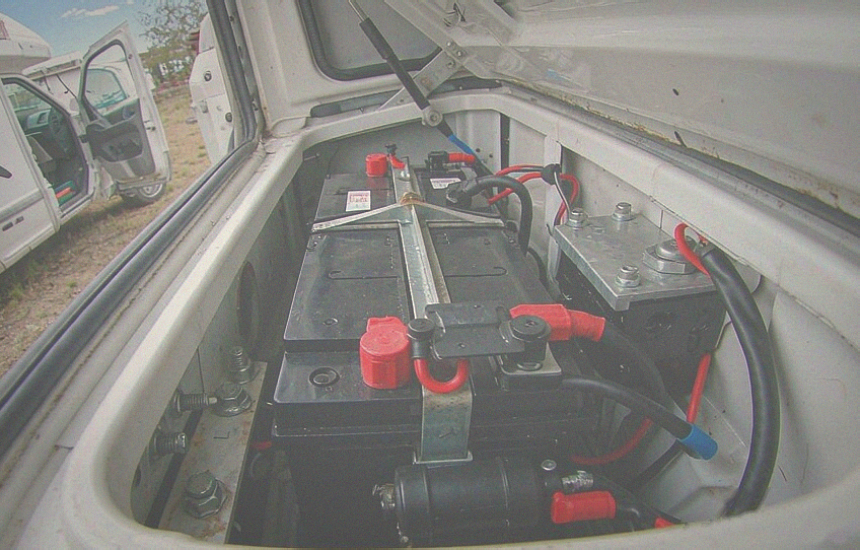
Building this into a new vehicle is engineering. Replacing an existing system is archaeology. The compartment was sized for a lead-acid block, the cables were run under the floor and through bulkheads, and the old wiring has to be traced before anything can be trusted. Add four charging sources that were installed at different times by different people, and the integration work easily exceeds the battery installation.
The lesson from builds like this is to plan the DC topology before ordering hardware: where the bank sits, where the inverter sits, how the four charge sources reach the busbar, and which circuits get their own disconnect. A one-page drawing saves weeks of work later, and it is also the document a future owner will need.
Monitoring a Large Reserve
With 9 kWh on board, the operator needs a single screen that answers three questions: how much is left, what is coming in, and what is going out. A shunt-based monitor provides the first two; a controller that aggregates every device provides the third and adds remote access. On a bus with a generator, knowing the state of charge before deciding whether to run it for an hour is the whole point of instrumentation.
Alarms matter more at this scale. A low state of charge alarm at 20 percent, a high voltage alarm below the BMS cutoff, and a temperature alarm that doubles as the charge-inhibit notification turn a passive dashboard into something that prevents damage while nobody is looking at it.
Specifying the Bank
UFOPOWER is a professional lithium battery manufacturer producing 12 V, 24 V and 48 V LiFePO4 packs for RV, marine and off-grid applications. For a reserve this size, three questions decide the specification: continuous and peak current (420 A and 840 A in this build), the charge voltage window shared by four sources, and what the BMS exposes so the system controller can see cell-level limits.
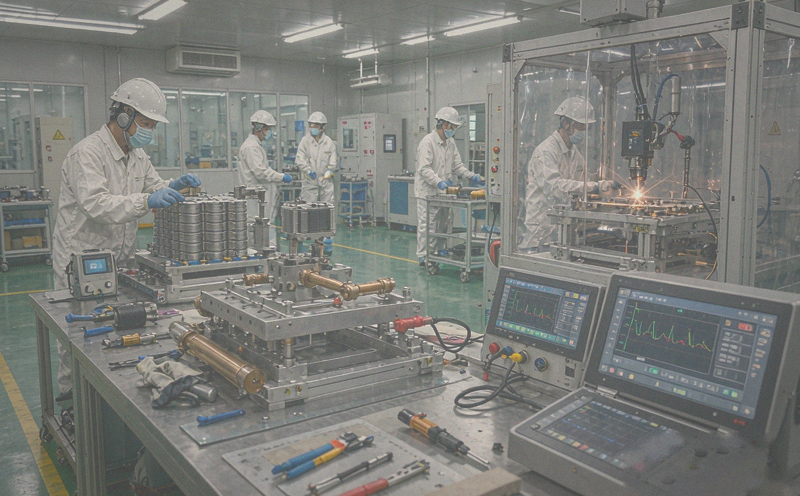
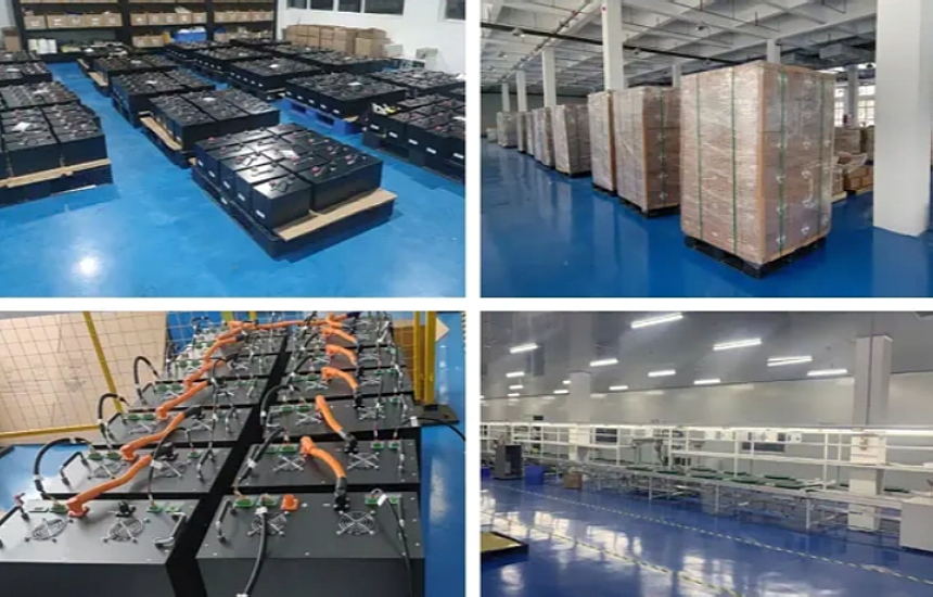
Packs are assembled with welded busbars, in-house BMS design, temperature-sensed charge protection and CAN or RS485 reporting, and every unit is capacity-tested and high-current discharge-tested against its serial number. OEM and ODM customization covers the enclosure and terminal layout that decides whether three batteries fit the compartment you actually have.
Send UFOPOWER the reserve you need, the inverter you are feeding and the charge sources you already own, and the answer comes back as a pack specification that matches all three instead of a datasheet that matches none of them.


 EN
 AR
 DE
 ES
 FR
 JP
 KO
 PT
 RU
 Главная >
 Nov 13, 2026





 в WhatsApp