
 Nov 17, 2026
Medical devices keep getting smaller, thinner and more portable, and the power source is now one of the hardest parts of the mechanical design rather than a component bought at the end of the project. A wearable insulin pump, a handheld diagnostic tool, a portable ultrasound console and a surgical stapler all need a pack that fits an irregular cavity, survives repeated disinfection and can be traced back to the material batch it came from. That combination is what the industry calls a custom LiPo battery for medical solutions, and it is a design and manufacturing problem, not a catalogue order.
This article follows a medical pouch pack from the requirement sheet to the shipping box: how thickness and capacity are balanced, why stacked electrodes are used instead of a wound jelly roll, what vacuum sealing and formation ageing actually control, and which documentation a device manufacturer should expect. UFOPOWER is a professional lithium battery manufacturer producing custom pouch packs for medical, wearable and portable equipment, with in-house production and OEM/ODM engineering support.
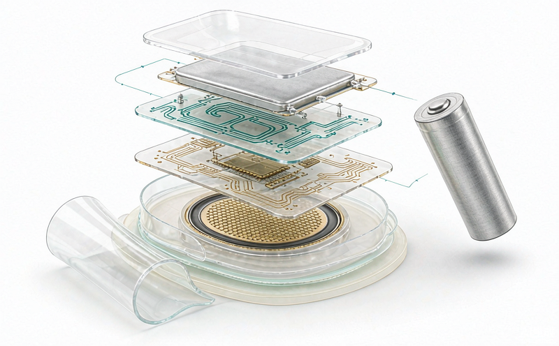
The cell inside a medical pack is often chemically similar to the cell inside a consumer device. What separates them is the discipline around it: which cell is selected and how tightly it is graded, how the pack is assembled and sealed, how much of the process is recorded, and how changes are controlled after the design is frozen. A consumer programme can tolerate a silent cell supplier change. A medical programme cannot.
| 차원 | Consumer pouch pack | Medical-grade pouch pack |
|---|---|---|
| Cell grading | Capacity band, sometimes voltage only | Capacity, internal resistance, self-discharge and voltage retention, matched within the pack |
| Process control | Sampling inspection | In-process controls at coating, stacking, sealing and formation, with recorded parameters |
| Traceability | Lot number on the pack | Serial or barcode on every cell, linked to electrode lot, separator lot, electrolyte batch and test data |
| Change control | Supplier decides | Written notification and re-validation before any cell, BMS or material change ships |
| Documentation | Datasheet and certificate of conformity | Specification, test reports, incoming and outgoing inspection records, failure analysis reports |
| 보호 | Pack protection IC, basic | BMS with cell monitoring, temperature sensing, communication and logged events |
Safety behaviour under abuse. A pouch cell has no rigid metal can. When a cell is overcharged, overheated or internally shorted, the sealed laminate pouch tends to swell and vent gas instead of rupturing a metal shell. That is a genuine advantage in a device worn on the body, but it is a design intent, not a guarantee: a pouch cell can still enter thermal runaway and burn. The pack must combine the pouch format with cell grading, protection electronics, a vent path and mechanical support, not rely on the pouch alone.
Energy density and thinness. Pouch construction removes the can wall, the mandrel and the void space around a round cell. Cells a few millimetres thick are routine, and thin formats let the pack follow the internal contour of a handheld device. The benefit is not only weight; it is that the battery stops dictating the industrial design.
Form factor freedom. Length, width, thickness and outline can be tooled to the enclosure, including stepped, curved and trapezoidal profiles. A cylindrical cell in a slim housing wastes the corners of the cavity; a shaped pouch uses them. The trade-off is tooling cost, minimum order quantity and a longer qualification cycle, which is why shape customisation should be decided early.
Medical pouch design usually runs backwards from the mechanical envelope. The engineer has a cavity, a target runtime and a weight limit, and needs to know whether the energy fits. A first-order estimate uses cell-level volumetric energy density in the range of roughly 350 to 450 Wh per litre for modern lithium pouch cells, then applies a pack-level factor of about 0.70 to 0.80 for packaging, protection board, insulation and swelling allowance. The estimates below are planning figures, not a specification.
| Device type | Cavity volume | Cell-level energy at 400 Wh/L | Pack-level at 75 percent | Resulting pack |
|---|---|---|---|---|
| Wearable telemetry, 30 x 25 x 4 mm | 3.0 cm3 | 1.2 Wh | 0.9 Wh | 1S, about 240 mAh at 3.7 V |
| Handheld diagnostic, 90 x 60 x 10 mm | 54 cm3 | 21.6 Wh | 16.2 Wh | 4S, about 1.1 Ah at 14.4 V |
| Portable ultrasound, 160 x 110 x 15 mm | 264 cm3 | 105.6 Wh | 79.2 Wh | 4S, about 5.5 Ah at 14.4 V |
Two conclusions follow. First, thinness is expensive in energy: halving the thickness halves the volume and therefore roughly halves the capacity, so a thin wearable pack is a runtime decision as much as a mechanical one. Second, the pack-level factor matters. On the portable ultrasound example, the difference between a 75 percent and an 85 percent packaging efficiency is about 10 Wh, which can be the difference between meeting the runtime target and missing it. That factor should be agreed with the pack supplier before the industrial design is signed off.
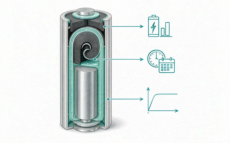
A medical pouch cell is not differentiated by a single machine. It is differentiated by how tightly four stages are controlled, and by what happens to the data they generate.
1. Slurry mixing and slot-die coating. Cathode material, conductive additive and binder are mixed into a slurry, and the same is done for the graphite anode. The coating weight and thickness uniformity control how current distributes across the electrode. A heavy spot becomes a hot spot, and a hot spot becomes the place where the cell ages first or fails first. Medical programmes normally require tighter coating tolerance and documented first-article approval, because a cell that is merely average at the start of life will drift out of balance in a multi-cell pack long before its rated cycle count.
2. Z-fold stacking. Electrodes and separator are stacked layer by layer in a Z pattern rather than wound into a jelly roll. Stacking gives a flatter current path, lower internal resistance and more even heat distribution, and it avoids the corner stress that winding imposes on the electrode edges. For a device that pulls short high-current bursts, such as a surgical stapler or a portable defibrillator, that lower resistance shows up directly as less voltage sag and less local heating.
3. Pouch forming, electrolyte injection and vacuum sealing. The stack is placed in a deep-drawn aluminium laminate pouch, electrolyte is injected under controlled humidity, and the pouch is vacuum sealed. The control objective here is moisture and gas: residual water reacts with the electrolyte and generates gas, which appears later as swelling and capacity fade. Dry-room dew point, sealing temperature and seal width are therefore process parameters, not housekeeping details.
4. Formation, ageing and traceability. New cells are charged slowly to build a stable passivation layer, then stored in temperature-controlled chambers for a defined ageing period while voltage, capacity and self-discharge are logged. Cells that drift are screened out before they enter a pack. Every cell carries a barcode that links it to the electrode lot, separator lot, electrolyte batch and test record, so a field issue can be traced back to a production window rather than to a whole year of output.
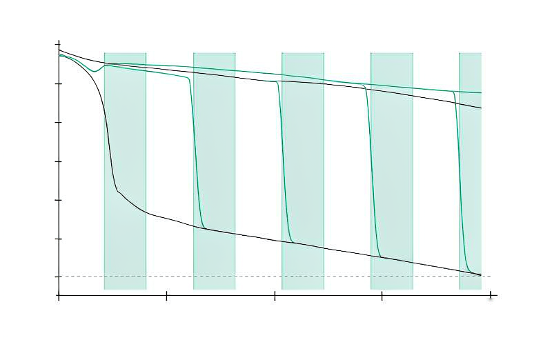
The choice between stacked and wound construction is usually presented as a manufacturing preference. In medical packs it is a performance decision, because it changes internal resistance, heat distribution and the mechanical stress the electrode sees over thousands of cycles.
| 인자 | Z-fold stacked cell | Wound (jelly roll) cell |
|---|---|---|
| Internal current distribution | Even, tabs distributed across the stack | Concentrated near the tabs, longer path at the far end |
| Internal resistance | Lower, better suited to high-rate pulses | Higher, more voltage sag under load |
| Heat distribution | Flat and uniform across the pouch face | Hot spots near the mandrel and tabs |
| Mechanical stress on electrodes | Low, no bending radius | Concentrated at the corners of the winding |
| Thickness control | Set by stack count, predictable | Set by winding tension, less predictable |
| Cost and throughput | Higher equipment cost, slower per cell | Lower cost, high throughput |
| Typical medical fit | High-rate devices, long-cycle implants and monitors | Cost-driven consumer products |
Most field complaints about medical packs are not cell failures; they are imbalance failures. One cell in a series string ages faster, the BMS cuts off early, the device reports a shorter runtime than the label, and the whole pack is replaced. The cause usually sits in screening, not in chemistry.
• Capacity matched within a tight band across the cells in one pack, not just within the datasheet tolerance
• Internal resistance and voltage compared after a defined rest period, so contact resistance and temperature differences do not distort the reading
• Self-discharge behaviour checked over an ageing window, since a cell that loses voltage faster than its neighbours will drag the string down
• Formation and ageing data retained per serial number, so a drift pattern can be traced back to a coating or electrolyte batch
For a 4S pack, a 2 percent capacity mismatch between cells is enough to reduce usable pack capacity well before any single cell reaches its cycle limit. That is why medical programmes often specify matching tighter than the cell datasheet requires.
A pouch pack has no built-in vent or current interrupt device, so the protection board carries more responsibility than in a cylindrical pack. A practical 4S configuration for a 14.4 V medical pack uses the following reference thresholds. These are starting points to be confirmed against the selected cell specification, not universal values.
| 매개 변수 | Reference setting (4S) | Purpose |
|---|---|---|
| Cell overcharge protection | 4.25 V per cell, release at 4.10 V | Prevent lithium plating and electrolyte breakdown |
| Cell over-discharge protection | 2.80 V per cell, release at 3.00 V | Avoid copper dissolution and deep-discharge damage |
| Continuous discharge limit | Set from the cell C-rate, with margin for device peaks | Keep the pack inside its thermal design envelope |
| Short-circuit protection | Hardware comparator, microsecond response | Protect the connector and the patient environment |
| Charge temperature window | 0 to 45 °C, with an inhibit outside the range | Stop charging a cold pack brought in from a vehicle |
| Discharge temperature window | -20 to 60 °C, derated at the extremes | Match the device's stated operating environment |
| Cell balancing | Start above 4.15 V, passive balancing | Keep the string aligned over the service life |
Two design choices matter more than the threshold numbers. First, protection should be redundant: the BMS protects the pack, and the device firmware independently stops the load before the BMS has to act. Second, the BMS should log events, not just switch off. A pack that records the last twenty fault events gives biomedical engineering a diagnosis; a pack that simply goes dark gives them a replacement request.
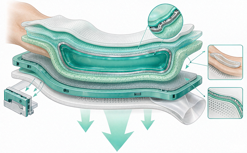
Medical pouch packs are usually assessed on three levels, and mixing them up is one of the most common delays in a device programme.
Cell and pack safety: IEC 62133-2 is the baseline for secondary lithium cells and batteries. UL 2054 and UL 1642 are the US counterparts that hospital procurement often asks for. These are pack-supplier documents.
Transport: UN 38.3 covers altitude, thermal cycling, vibration, shock, external short, impact, overcharge and forced discharge. Every shipment needs the test summary, and a pack that changes cell or protection design may need re-testing. This is also a pack-supplier document.
Device-level safety: IEC 60601-1 and, for home-use devices, IEC 60601-1-11 belong to the device manufacturer. The pack supplies design input: protection thresholds, temperature limits, fault behaviour and test evidence. A battery supplier claiming to certify a device to 60601 is overstating its scope, and that is worth checking during supplier qualification.
Quality system is a separate question. If the device programme requires ISO 13485 at the pack supplier, review the actual certificate scope and the audit history rather than accepting a logo on a website. UFOPOWER supports customer audits with process records, incoming and outgoing inspection data and per-serial test files, and can provide IEC 62133-2 reports and UN 38.3 test summaries for evaluation.
The projects that finish on schedule treat the battery as a workstream with gates, not as a purchase order. A typical sequence looks like this.
| Gate | What is decided | Deliverable |
|---|---|---|
| G0 Requirements | Cavity, runtime, load profile, environment, cleaning agents, certification route | Battery requirement specification |
| G1 Concept | Series count, cell format, capacity estimate, protection architecture, connector | Pack concept drawing and preliminary BMS block diagram |
| G2 Prototype A | Fit, thickness, retention, connector position, service access | Form and fit samples in the real enclosure |
| G3 Design validation | Capacity and runtime at the rated load, temperature rise, drop, ingress after cleaning, charge inhibit | Validation report and design freeze |
| G4 Certification and pilot | 62133-2 and UN 38.3 evidence, device-level 60601 input data, pilot build | Test reports, pilot lot with full traceability |
| G5 Mass production | Lot release criteria, change notification, service spares plan | Serial-level records and agreed end-of-life process |
• Specifying the cavity before the runtime and load profile are fixed, then discovering the energy does not fit
• Assuming zero cell growth over life, so a swollen pack jams in the bay in year three
• Choosing a custom outline that no second source can tool, creating a single point of failure
• Leaving cleaning agents out of the specification, then failing the seal after repeated disinfection
• Treating IEC 60601-1 as a battery certificate instead of a device-level assessment that needs pack data as input
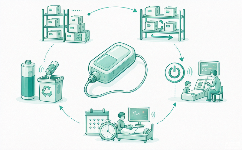
A medical LiPo pack is not a commodity cell with a wire attached. It is a shaped mechanical part, a sealed chemical system, an electronic protection layer and a documentation trail, and all four have to be designed together. The pouch format gives the thinness and shape freedom that portable and wearable devices need, while stacked electrodes and tight process control supply the low internal resistance and the consistency that clinical use demands.
The practical test for a supplier is not the datasheet. It is whether they can explain their coating tolerance, their stacking process, their sealing and ageing controls, their matching criteria and their traceability down to the electrode lot, and whether they will put a change notification clause in writing. UFOPOWER builds custom medical and industrial pouch packs with in-house production, factory-direct OEM and ODM service, and engineering support from cavity measurement through validation and serial-level traceability.
If you are starting a medical device programme, send the cavity drawing, the load profile and the cleaning and certification requirements, and the engineering team will return a pack architecture with the thickness budget, protection plan and test route attached.
What makes a LiPo battery medical-grade rather than consumer-grade?
Why use Z-fold stacking instead of a wound cell?
How thin can a custom medical LiPo pack be?
Can a pouch pack be shaped to fit an irregular enclosure?
Do medical LiPo packs need a BMS?
How is traceability handled in a medical battery pack?
Does IEC 60601-1 certify the battery?


 WhatsApp의
 EN
 AR
 DE
 ES
 FR
 JP
 KO
 PT
 RU
 홈 >