A patient monitor that goes dark during a transfer, an infusion pump that stops mid-delivery, a defibrillator that will not charge when the cart reaches the patient: in medical equipment a battery failure is not an inconvenience, it is a clinical event. That is why the LiPo versus Li-ion question comes up in almost every device programme, and why it is usually asked in the wrong form. The useful question is not which chemistry name sounds safer, but which cell format and pack architecture keeps a specific device working through its worst-case day.
This article compares LiPo pouch cells and cylindrical Li-ion cells on the safety factors that matter in medical design: swelling, mechanical protection, thermal runaway, high-rate discharge, charging logic and documentation. UFOPOWER is a professional lithium battery manufacturer building custom packs for medical, industrial and portable equipment, so the comparison below is written from the pack side of the project rather than from a chemistry datasheet.
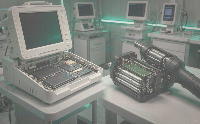
The Short Answer: Neither Format Is Inherently Safer
A correctly engineered lithium pack is safe, and an incorrectly engineered one is not, regardless of whether the cells are flat pouches or metal cans. Safety comes from the complete system, and a medical pack should document each of these layers before the design is frozen:
• Cell chemistry and cell supplier qualification
• Cell selection, grading and matching for the pack
• Protection circuit and, where used, a battery management system
• Charging control matched to the exact cell and series count
• Thermal management and temperature sensing
• Mechanical protection against drop, crush and puncture
• Short-circuit, overcharge and over-discharge protection
• Manufacturing quality control and lot traceability
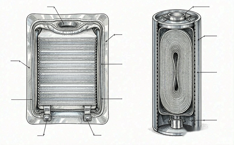
The genuine difference between the two formats sits in physical construction, and that difference changes which failure mode you have to design against. A pouch cell fails visibly and gradually in many cases. A cylindrical cell fails later and less visibly, but tolerates abuse better before it does.
Pouch vs Cylindrical: What Actually Differs
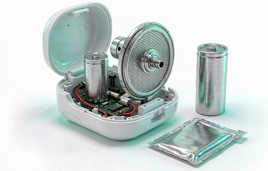
One clarification first, because it affects every specification you write. LiPo is a packaging description, not a chemistry. A lithium polymer pouch cell typically uses the same lithium nickel manganese cobalt or lithium cobalt oxide active materials as a cylindrical cell, formed into a flat stack and sealed inside an aluminium laminate film. Cylindrical cells are the familiar 18650, 21700 and 26650 formats with a rigid steel or aluminium can, a built-in vent and welded tabs. Prismatic cells sit between the two: a hard plastic or aluminium case around a stacked or wound electrode assembly.
In practice this means a pouch pack and a cylindrical pack of the same chemistry have similar energy per kilogram at cell level, but very different behaviour at pack level. The pouch gives you the shape; the can gives you the armour.
| Safety factor | LiPo pouch cell | Cylindrical Li-ion cell |
|---|
| Cell structure | Flexible aluminium laminate pouch | Rigid steel or aluminium can |
| Mechanical protection from the cell itself | Low, depends on enclosure and compression | High, the can absorbs compression |
| Weight at pack level | Lower, no cans and less void space | Higher, cans plus holders and spacing |
| Shape flexibility | Length, width and thickness to order | Fixed standard diameters and heights |
| Swelling visibility | Usually obvious before failure | Hidden inside the can until venting |
| Resistance to puncture and crush | Lower, laminate film is thin | Higher, but a dented can may short internally |
| Descarga de alta taxa | Excellent, large electrode area with short current paths | Excellent, depends on tab and mandrel design |
| Space efficiency in thin devices | Very high, fits around internal ribs | Poor, round cells waste volume |
| Thermal management approach | Flat compression pads and heat spreaders | Cell holders, spacing and airflow paths |
| Second-source availability | Custom size, usually one qualified source | Multi-vendor standard sizes |
| Typical medical fit | Monitors, pumps, wearables, handheld ultrasound | Surgical tools, carts, backup modules, high-vibration housings |
Why Medical Equipment Raises the Bar
A power tool that dies is annoying. A ventilator that dies is a patient safety report. Four characteristics of medical devices change the battery specification compared with consumer or industrial products.
Essential performance. Medical electrical equipment is assessed on whether it maintains essential performance or fails in a defined safe state. A pack that simply cuts off at low voltage may be acceptable in a torch and unacceptable in an infusion pump, where the device must alarm, log the event and complete a controlled stop.
Service life of five to ten years. The device outlives several batteries. The pack must be replaceable, keyed so it cannot be fitted to the wrong device, and specified with a replacement interval based on cycle count and calendar ageing, not on the warranty period.
Repeated disinfection. Quaternary ammonium wipes, isopropyl alcohol and hydrogen peroxide are routine. Steam autoclaving at 134 °C is not a battery process. The pack seal, label adhesive and connector plating have to survive the cleaning agent list in the device instructions for use, not just one wipe.
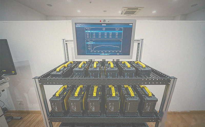
Centralised charging and shared inventory. Hospitals charge dozens of packs in one cabinet, often unattended and at ambient temperatures well above office conditions. A single pack that vents in that cabinet affects every device in the fleet, which is why pack-level protection and a visible condition check matter more than cell-level claims.
Matching the Format to the Device
The same pouch cell that is the right answer in a 12 mm thick monitor is the wrong answer in a surgical drill that gets dropped on a tiled floor. Reference configurations below are typical starting points for a design review; the final pack must be derived from the device load table and the mechanical envelope.
| Device group | Reference pack | Duty profile | Format that usually wins |
|---|
| Patient monitor | 14.4 V, 4 to 6 Ah, 60 to 90 Wh | 10 to 25 W continuous, 2 to 4 h runtime | Pouch, thin enclosure behind the display |
| Infusion pump | 12 V, 2 to 4 Ah, 25 to 50 Wh | Low continuous current, 4 to 8 h runtime | Pouch, low self-heating, sealed against fluid ingress |
| Ventilator | 24 V, 6 to 10 Ah, 150 to 250 Wh | 30 to 60 W with compressor peaks | Pouch or prismatic, space and weight driven |
| Defibrillator and AED | 12 to 24 V, high-rate pack, 100 to 200 Wh | Long standby, seconds of very high power | High-rate pouch or cylindrical, both used in service |
| Portable ultrasound | 14.4 V, 6 to 10 Ah, 90 to 150 Wh | 20 to 40 W, burst transmit peaks | Pouch, thin tablet-style housing |
| Surgical power tool | 24 V, 2 to 4 Ah, 50 to 100 Wh | 100 W continuous, 250 W peak, drop exposed | Cylindrical, rigid can and standard cells |
| Wearable telemetry | 3.7 V, 1 to 3 Ah, 4 to 11 Wh | Milliwatts, 24 to 72 h runtime | Small pouch or coin, body-worn comfort |
Swelling: The Pouch Failure Mode That Shows Up Early
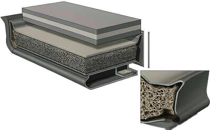
A pouch cell can generate gas internally as it ages or is abused, and the laminate film has nowhere to hide the expansion. In a medical device that shows up in ways maintenance staff notice: the battery latch no longer closes flush, the rear housing bulges, a sealed seam opens, or the pack no longer slides into its bay. That is a useful early warning, provided the device design allows it to be seen.
Common causes of swelling are cell ageing, overcharging, sustained high temperature, internal degradation, mechanical damage, manufacturing defects and charging outside the specified conditions. The correct field response is always the same: the pack is removed from service, tagged, and handled under the site battery procedure. It is never returned to a patient-facing device simply because the device still powers on.
For the mechanical engineer, five provisions make the difference:
• Reserve thickness allowance in the bay for cell growth over life, and confirm the figure with the cell supplier rather than assuming zero growth
• Use compression pads that keep the stack flat without clamping the pouch rigidly
• Keep sharp ribs, screw bosses and cable ties away from the pouch face
• Provide a gas path so a venting cell does not pressurise the device enclosure
• Add a go/no-go thickness check to the annual service procedure
Mechanical Damage, Cleaning and Drop
Cylindrical cells win the direct abuse comparison, but the advantage is narrower than it looks. A metal can resists compression and handling damage, yet a dented can deforms the electrode stack inside and can create an internal short that only shows up weeks later. Pouch cells have no such protection, so the pack enclosure carries the load: ribbed walls, foam or silicone compression, and a retention design that prevents the pack sliding on its connector during a drop.
Test to the environment the device actually meets, not to a generic consumer standard: cart vibration across thresholds and lift columns, a free-fall sequence onto hard flooring with the pack installed, connector pull and insertion cycle tests, and a fluid ingress check after the cleaning cycle. Sealing is where medical packs most often fail in the field, because the gasket that passed the initial ingress test is compressed hundreds of times over the device life.
Cleaning chemistry needs to be in the pack specification too. Alcohol attacks some label adhesives and printed films. Hydrogen peroxide and quaternary ammonium compounds attack certain elastomers. If the pack is wiped rather than immersed, say so explicitly in the instructions and verify the IP rating under that condition, not under immersion.
Thermal Runaway: Assume a Cell Can Fail and Design for It
Thermal runaway is a self-accelerating reaction: heat drives further exothermic decomposition, which produces more heat. Triggers include internal short circuits, severe overcharge, external heating, mechanical damage and manufacturing defects. It is not a pouch problem or a cylindrical problem. Pouch, cylindrical and prismatic cells can all enter runaway, and a rigid can does not remove the possibility.
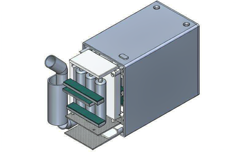
Medical pack design therefore works on two fronts at once. First, prevent the conditions that initiate failure: cell grading, per-cell voltage monitoring, charge inhibit outside the temperature window, fusing of parallel strings, connector keying to stop wrong chargers. Second, limit the consequence if a cell does fail: spacing or barriers between cells, flame-retardant enclosure material, a vent path that directs gas away from the patient side of the device, and temperature sensors placed between cells rather than on the pack surface.
The device firmware has a role too. A pack that reports an abnormal cell group should trigger an alarm and a controlled shutdown while the device still has reserve, rather than waiting for the protection circuit to cut power at the last moment.
| Failure mode | What happens inside the cell | Pack-level control |
|---|
| Overcharge | Voltage above the specified limit, electrolyte breakdown, gas and heat | Per-cell monitoring, independent redundant cutoff, charger handshake |
| Over-discharge | Copper dissolution, capacity loss, plating risk on recharge | Low-voltage cutoff, sleep current limit, storage mode |
| External short circuit | Very high current through a low-resistance path, rapid heating | Fuse, current-limited output, protected connector pins |
| Internal short circuit | Defect, contamination or lithium plating bridges the electrodes | Cell qualification, formation screening, barriers and spacing |
| Over-temperature | Charge or discharge outside the allowable window accelerates ageing | NTC sensors per cell group, charge and discharge inhibit, thermal fuse |
| Cell imbalance | One group drifts, the weakest cell limits the pack and can be over-stressed | Balancing, state of charge and state of health estimation, service alert |
| Mechanical abuse | Crush, puncture or drop deforms the electrode stack | Ribbed enclosure, foam compression, pack retention, drop validation |
High-Rate Events: Defibrillation and Surgical Tools
Two medical applications push cells harder than any monitor, and they demand opposite pack designs. A defibrillator delivers 200 J to the patient in a few milliseconds. At about 85 percent conversion efficiency the pack must supply roughly 235 J. Across a 14.4 V pack that is about 16.3 A·s of charge, and if the capacitor charges in five seconds the average draw is only 3.3 A, with a much higher peak. Ten shocks in a resuscitation sequence total about 2,350 J, or 0.65 Wh, which is a fraction of the pack capacity.
The lesson is that defibrillator packs are not energy problems, they are power problems. Cell choice, tab design, internal busbar cross-section and connector contact resistance dominate. A larger pack with high-impedance cells performs worse than a smaller pack built for high-rate discharge.
A surgical power tool is the reverse case: sustained power in a housing that gets dropped. At 100 W on a 24 V pack the draw is about 4.2 A, and a 250 W stall or peak takes it to roughly 10.4 A. On a 3 Ah pack that is over 3C, which is why voltage sag under load, connector heating and cell balance all show up as a tool that feels weak at the end of a long procedure. Here cylindrical cells with a rigid can, a proper holder and a mechanical latch earn their weight penalty.
AEDs add a third constraint: years of standby with self-test pulses and almost no cycling. That is a calendar-life and self-discharge problem rather than a cycle-life problem, and it makes sealed construction, a dated replacement schedule and a pack-level self-test log more important than the cell format.
Charging Architecture and BMS in a Hospital Environment
Charging is the single most common root cause in lithium battery incidents, and in medical equipment the charger is usually shared across a fleet. The pack and charger should be designed as one system: correct charge voltage for the exact series count, current limit within the cell specification, charge termination by current taper rather than by timer, balancing during the constant-voltage phase, and a temperature inhibit that blocks charging outside the window. LiFePO4 packs must not be charged below 0 °C, a rule that matters when devices come in from a cold ambulance bay.
In a central charging cabinet, three operational rules prevent most problems: do not stack packs so that heat from one warms another, keep the cabinet ambient within the pack specification rather than the corridor temperature, and remove any pack that is swollen, damaged or has a failed self-test before it goes on charge. The BMS should log cycle count, cell voltages, temperature extremes and state of health so the biomedical engineering team can schedule replacement from data instead of from failure reports.
For a pack with a state of health estimate, a service alert at around 80 percent of beginning-of-life capacity is a practical planning threshold for devices that must complete a defined runtime on battery. That figure is an operating decision for the device manufacturer, not a warranty definition, and it should be written into the service manual.
Standards and Documentation
Medical battery compliance is split between the cell, the pack and the device, and a supplier who cannot say which document covers which level is a risk in itself. The table below is the working map used in pack specifications.
| Padrão | What it covers | Who owns the evidence |
|---|
| IEC 62133-2 | Safety of secondary lithium cells and batteries, including overcharge, forced discharge, external short, impact, crush, thermal abuse and temperature cycling | Cell maker and pack maker, report available to the device maker |
| IEC 60601-1 | General safety of medical electrical equipment, including the battery as part of the equipment and essential performance | Device manufacturer, with pack data as design input |
| IEC 60601-1-11 | Home healthcare environment, relevant to portable and home-use devices | Device manufacturer |
| UN 38.3 | Transport of lithium cells and batteries: altitude, thermal, vibration, shock, external short, impact, overcharge, forced discharge | Cell and pack supplier, summary provided with shipment |
| UL 2054 and UL 1642 | US safety standards for battery packs and lithium cells, often required by hospital procurement | Cell and pack supplier |
| IEC 60529 and IEC 60068-2-32 | Ingress protection and free-fall test methods for the pack enclosure | Pack maker, verified in the device context |
| ISO 13485 and ISO 14971 | Device quality management and risk management, which pull the battery into the risk file | Device manufacturer |
UFOPOWER can provide UN 38.3 transport test summaries and IEC 62133-2 reports for evaluation, together with lot traceability and incoming and outgoing inspection records. Device-level 60601 assessment remains with the device manufacturer, and the pack data is supplied as design input for that file.
Design Input Checklist for a Custom Medical Pack
Whether the choice lands on pouch or cylindrical, the specification should be built from four groups of inputs before any cell is selected. A pack chosen from a capacity number alone will usually be redesigned twice.
Electrical. Nominal voltage and operating range, capacity at the specified discharge rate, continuous and peak discharge current, charge current, required runtime at the defined load, standby current and self-discharge allowance over the service interval.
Mechanical. Maximum length, width and thickness, weight limit, connector type and keying, latch and insertion cycle count, drop and vibration profile, and the space reserved for cell growth.
Environmental. Operating and storage temperature, humidity, ingress protection level, the actual cleaning agent list, altitude, and whether the device is used in a home healthcare setting.
Protection and documentation. BMS or PCM functions, sensor placement, fusing strategy, alarm and communication interface, plus lot traceability, test records, change notification and end-of-life handling.
As a professional lithium battery manufacturer, UFOPOWER builds these inputs into a pack specification and a validation plan before sampling, because a medical customer cannot accept a pack that passes capacity but fails the drop, seal or charge-inhibit requirements.
Six Rules That Apply Whichever Format You Choose
• Use qualified cells from a controlled supply chain, graded and matched for the pack, not surplus or unverified stock
• Match the charger to the exact chemistry and series count, and treat an incompatible charger as a design defect
• Protect the pack mechanically: no puncture, no crush, no bending, no unsupported pouch face
• Keep charging and discharging inside the specified temperature window, with an inhibit that actually blocks charge
• Integrate protection electronics for overcharge, over-discharge, over-current, short circuit, temperature and balancing
• Validate electrically, mechanically, environmentally and for safety before mass production, and re-validate after any cell or BMS change
Conclusion: The Pack Is the Safety System
There is no universal winner between LiPo and Li-ion in medical equipment. The pouch format gives the thin, light, shape-fitted pack that modern monitors, pumps and handheld imaging devices need, and it fails visibly through swelling, which is an advantage if your service procedure checks for it. The cylindrical format gives a rigid, standardised, multi-source cell that survives abuse and simplifies the mechanical design, at the cost of volume and weight.
What decides patient safety is the complete chain: cell chemistry plus cell quality plus format plus protection circuit plus BMS plus charger plus thermal design plus mechanical design plus manufacturing quality. A supplier who evaluates voltage, capacity, discharge current, dimensions, temperature, cleaning exposure and protection requirements together, and who can produce the test documentation behind each claim, is worth more than a lower quotation on cells alone.
UFOPOWER supplies factory-direct custom lithium battery packs for medical and industrial equipment, with OEM and ODM support from cell selection through enclosure, BMS configuration, validation and lot traceability. If you are choosing between pouch and cylindrical for a new device, send the load table, the mechanical envelope and the cleaning requirements, and the engineering team will return a pack architecture with the protection and documentation plan attached.


 EN
 AR
 DE
 ES
 FR
 JP
 KO
 PT
 RU
 Página inicial >
 Nov 18, 2026







 aplicativo WhatsApp