
 Sep 02, 2026
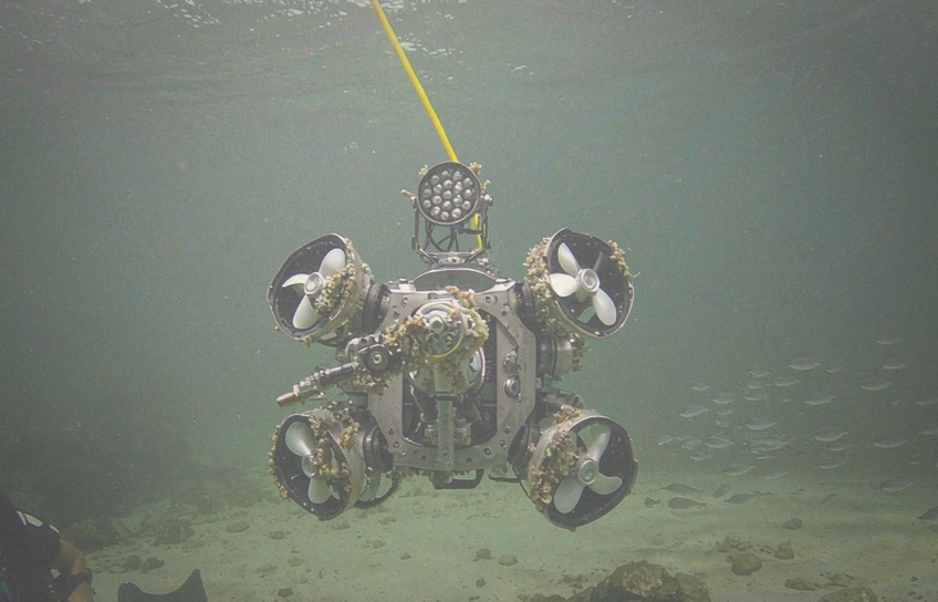
A 로 전문 리전يوم 배터리 제조업체UFOPOWER은 개발자들과 협력합니다. AUV 배터리, ROV 배터리그리고 전 세계의 수중 로봇 전력 시스템.배터리 시스템은 수중 로봇을 개발할 때 고려해야 할 첫 번째 시스템 중 하나입니다. 선체와 추진 시스템이 이미 완성된 후 선택할 부품이 아닙니다.배터리 전압은 추진 시스템과 전력 전자기에 영향을 미칩니다.용량은 임무 시간, 무게 및 부동력에 영향을 미칩니다.세포 형식은 압력 하우징 이용에 영향을 미치지만 BMS, 연결기, 충전기 및 열 경로는 차량과 함께 작동해야합니다.rsquo는;전기 및 기계 건축.
우드스 홀 해양학 연구소는 더 강한 압력 하우징이 무게를 추가하므로 더 많은 부동력이 필요하며 차량 에너지 소비를 증가시킬 수 있다고 지적합니다.원형 압력 하우징은 날카로운 모서리를 가진 구조보다 외부 압력을 더 균등하게 분배하기 때문에 널리 사용됩니다.이것이 많은 AUV, 배터리 전원 ROV, 수중 트러스터 및 해중 장비 개발자가 표준 배터리 팩보다 더 많은 것을 필요로하는 이유입니다.세포 선택, 전기 건축, BMS 개발, 구조적 통합, 테스트 및 생산 계획에 참여할 수 있는 배터리 파트너가 필요합니다.
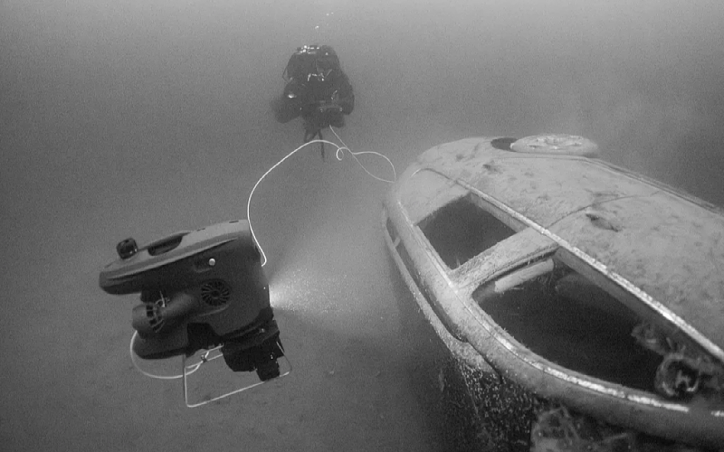
배터리 프로젝트는 질문으로 시작해서는 안됩니다. &ldquo는;18650 또는 21700 세포를 사용해야 합니까? & amp;rdquo는그것은 수중 로봇과 시작해야합니다.rsquo는;S 임무.엔지니어링 팀은 먼저 이해해야합니다.
차량 유형 및 응용
목표 임무 기간
크루즈 및 최대 속도
명목적 및 최대 시스템 전압
평균 작동 전력
연속 및 피크 전류
내부 배터리 구간 크기
작동 및 충전 온도
목표 깊이 및 압력 하우징 설계
충전, 도킹 또는 배터리 교환 방법
통신 프로토콜
필요한 기초 또는 비상 표면 예비
에너지와 임무 성능 사이의 관계는 설립된 연구 차량에서 볼 수 있습니다.우즈 홀 해양학 연구소&rsquo는;ABE 자율주행 수중 차량은 5kWh 리55리5kWh 리5555kWh 리ABE 55kWh의 리ABABE 자율주행 수중 차량은 5kWh의 리ABABE ABE 자율주행 수중 차량은 5kWh의 리5kWh 리5kWh 리5kWh 리5kWh의 리차량&rsquo는;s 센서만 연속적인 &를 만들었습니다.ldquo는;호텔 load&rdquo는그것은 에너지 예산에 포함되어야 했다.
따라서 같은 명목적 전압을 사용하는 두 개의 수중 로봇은 매우 다른 배터리를 필요로 할 수 있습니다.아래 표는 일반적인 차량 유형의 배터리 우선순위를 비교합니다.
| 차량 유형 | 전형적인 임무 | 배터리 우선순위 |
|---|---|---|
| 장거리 매핑 AUV | 대영역 설문 조사 및 자율 데이터 수집 | 에너지 밀도 및 낮은 무게 |
| 트러스터, 조명, 조작기를 가진 ROV | Close-up industrial inspection and intervention | Strong peak-current capability and a stable voltage platform |
| Resident subsea robot | Long-term deployment on the seabed | Low BMS standby consumption, service life, fault records, underwater charging |
Cylindrical cells such as 18650 and 21700 are standardized, widely available, and convenient for modular assembly. Their fixed dimensions can simplify sourcing, but a high-capacity pack may require many cells, welds, current paths, and mechanical supports. Pouch cells allow capacity, thickness, width, and length to be adjusted around the available space. They can be arranged as narrow modules, segmented packs, or large-capacity single-cell sections inside a cylindrical pressure housing.
Cell-format research (University of Bologna) shows that cylindrical, prismatic, and pouch formats create different tradeoffs in packaging efficiency, thermal behavior, mechanical support, manufacturing, and system-level energy density. No format is automatically best for every vehicle:
| Cell Solution | Main Advantage | Suitable Underwater Applications | Main Tradeoff |
|---|---|---|---|
| 18650/21700 cylindrical | Standard dimensions and mature modular assembly | Platforms already designed around cylindrical cell holders | More cells and interconnections may be required |
| Semi-solid-state pouch | High energy density and lower weight for a given energy target | Long-endurance AUVs and weight-sensitive underwater robots | Power capability and cost must be evaluated for each project |
| High-rate pouch | Low internal resistance and strong continuous or peak output | Battery-powered ROVs, thrusters, manipulators, and underwater tools | Lower energy density than high-energy cells |
| LiFePO4 pouch | Good thermal stability and long service potential | Commercial ROVs, monitoring systems, and subsea backup power | Higher weight and volume for the same stored energy |
UFOPOWER’s main advantage is not commodity cylindrical-cell supply. It is the ability to develop high-energy and high-power pouch solutions. The company’s semi-solid-state portfolio covers selected energy-density platforms from 300 to 380 Wh/kg, while its broader cell portfolio includes high-discharge-rate, LiHV, low-temperature, custom-shaped, and LiFePO4 options. The final value at pack level will be lower after adding the BMS, connector, wiring, enclosure, and mechanical protection.
LiFePO4 may be considered when thermal stability and service life are more important than minimum weight. Tests presented at the NASA Aerospace Battery Workshop found lower maximum temperatures for the evaluated LFP batteries than for the evaluated NMC batteries under thermal-runaway conditions, while also showing that module layout and heat-transfer paths strongly influence the complete pack response.
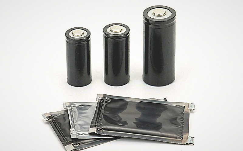
Series and parallel configuration connects cell characteristics to vehicle-level voltage, capacity, and power. Cells connected in series increase pack voltage while retaining the capacity of one series string. Cells connected in parallel increase amp-hour capacity and distribute current across multiple cells. Research on lithium-ion module configurations (U.S. Department of Energy) shows that series-parallel architecture affects current distribution, voltage spread, energy throughput, and degradation behavior, especially when cells are not perfectly matched.
For example:
A 6S standard lithium battery has a nominal voltage of approximately 22.2 V.
A 12S standard lithium battery has a nominal voltage of approximately 44.4 V.
Two 30 Ah strings connected in parallel provide a nominal capacity of 60 Ah, provided the cells and current paths are properly matched.
Electrical power follows P = V × I. For the same required power, a higher-voltage system can operate at a lower current. This can reduce resistive losses in cables and connectors, because those losses increase with the square of current (P loss = I²R). Higher voltage is not automatically better — it may require a higher-voltage motor controller, charger, BMS, insulation system, contactor, and connector. More parallel cells can increase capacity and output capability, but they also add weight, volume, interconnections, and cell-consistency requirements. The correct architecture should be determined together with the propulsion system, control electronics, charger, connector, and available housing space.
Battery capacity is normally stated in amp-hours, but underwater robot energy should also be evaluated in watt-hours: Energy (Wh) = Nominal Voltage (V) × Capacity (Ah). Mission time depends on usable energy, not Ah alone. The energy model must include propulsion, onboard computers, cameras, lights, sonar, communications, manipulators, pumps, and other auxiliary loads. Vehicle speed, water current, hydrodynamic drag, motor efficiency, temperature, aging, and the required recovery reserve also affect the result.
A practical preliminary estimate is: Required Energy = (Average Power × Mission Time) ÷ (Usable Depth of Discharge × System Efficiency). An engineering reserve should then be added for return, surfacing, unexpected currents, route changes, and battery aging. Long-range AUV research (NOAA Institutional Repository) treats endurance, route planning, navigation, and data transfer as connected system-level constraints rather than independent specifications.
Cold water must also be included in the calculation. Lithium-ion batteries can lose available capacity and power at low temperatures because ion transport slows and internal resistance increases. Laboratory research supported by Purdue University and the U.S. Department of Energy documented substantial capacity reductions as test temperature decreased, showing why room-temperature capacity cannot be used as the only basis for cold-water mission planning.
An underwater robot rarely operates at one constant current. Cruising may create a moderate load, while thruster startup, rapid maneuvering, station keeping in strong currents, manipulator movement, or simultaneous tool operation can produce short power peaks. The battery specification should distinguish:
Average current
Continuous current
Peak current
Peak duration
Minimum acceptable system voltage
Maximum BMS and connector temperature
A battery may have sufficient nominal capacity but still fail to support the propulsion system if its internal resistance is too high. A large current pulse can pull the terminal voltage down far enough to reduce thruster performance, trigger BMS protection, or restart vehicle electronics. Research on underwater thruster control has specifically identified battery voltage sag as a factor that can limit available thruster output. Power capability must therefore be checked across the complete current path: cell, busbar, weld, fuse, BMS, cable, connector, and motor controller. Charge rate, discharge rate, temperature, and calendar time also affect battery degradation, which is why DNV recommends controlled and transparent cell-testing methods when comparing battery performance (DNV-RP-0577).
UFOPOWER’s high-rate pouch-cell and industrial UAV experience provides a useful engineering base for underwater thrusters and battery-powered ROVs. Both applications involve motor loads, high current, voltage stability, connector heating, and limited weight. The actual discharge rate still needs to be confirmed from the robot’s measured or simulated load profile.
The cell is only one part of an underwater battery system. The pack also needs mechanical support, insulation, wiring control, BMS placement, thermal paths, sealing interfaces, and protection against vibration and impact. Cylindrical pressure housings are common because their geometry distributes external pressure efficiently. At an average seafloor depth of 3,800 meters, hydrostatic pressure is roughly 380 times atmospheric pressure at sea level. Housings for batteries and electronics must therefore be engineered around the target depth rather than treated as ordinary waterproof enclosures.
UFOPOWER has developed rugged smart battery packs for agricultural and industrial UAVs. Existing products combine BMS functions, thermal design, structured enclosures, high-current interfaces, and water-resistant construction for demanding outdoor operations. Several of these practices transfer directly to underwater projects:
Sealing around screws and enclosure joints
Waterproof power and data connectors
Sealing rings around buttons and service interfaces
Sealed cable exits with strain relief
Internal insulation and moisture barriers
Controlled placement of gaskets and sealing plugs
Shock-absorbing supports around cells and circuit boards
Water resistance is not the same as deep-water qualification. Agricultural and cleaning drones primarily face rain, spray, cleaning liquids, vibration, and repeated field handling. An underwater robot must also withstand continuous immersion, hydrostatic pressure, pressure cycling, saltwater corrosion, seal compression, and long-term material aging. Waterproofing and pressure resistance should therefore be validated at the complete battery enclosure or vehicle level. The same rule applies to vibration and impact performance: experience from UAV and high-power battery packs can guide material selection and structural design, but the final underwater configuration requires project-specific testing.
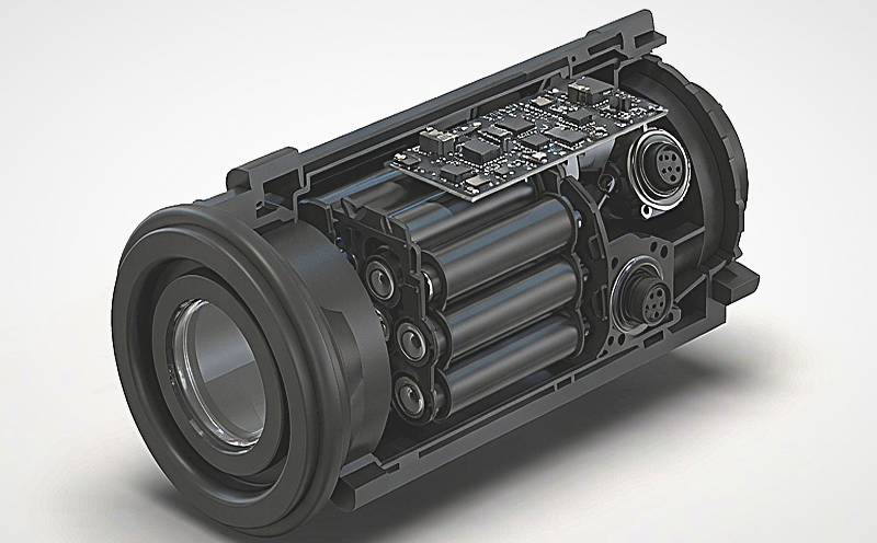
An underwater battery connector must be selected by more than pin count. Engineers need to consider voltage, continuous and peak current, contact resistance, wire gauge, locking method, mating cycles, corrosion resistance, sealing, and communication requirements. Power, charging, and data may use separate interfaces or a combined connector. Some systems are connected only in a dry environment, while subsea docking or service systems may require wet-mate technology. IEEE research on subsea power and data transmission treats wet-mate connection as a dedicated underwater engineering problem, not a standard extension of an exposed electrical plug.
UFOPOWER works with XT90S, AS150, AS150U, EC-series, Molex, and customized smart interfaces in UAV and industrial battery systems. These provide experience in high-current delivery, anti-spark design, locking, signal contacts, and BMS communication. A standard UAV connector should not be presented as subsea-ready unless its sealing and pressure performance have been verified for the intended environment.
A BMS monitors and controls the battery, but it is not the complete thermal-management system. Typical BMS functions include cell-voltage monitoring, current measurement, temperature monitoring, overcharge and over-discharge protection, overcurrent and short-circuit protection, balancing, SOC estimation, fault records, and communication. NASA describes cell monitoring, charge balancing, fault detection, and overvoltage or undervoltage protection as core functions of high-voltage battery management.
Thermal management deals with how heat moves through the pack. It includes sensor placement, cell spacing, thermal pads, heat spreaders, insulation, enclosure materials, and the conduction path from the cells to the pressure housing. NASA battery research emphasizes that pack energy, series-parallel layout, charging and discharging behavior, enclosure design, operating environment, and thermal conductivity all affect the thermal solution. There is no single architecture that fits every battery pack.
Cold seawater does not guarantee that a sealed battery pack will remain cool. Heat still needs to travel from the cell through the support structure and enclosure before it can reach the surrounding water. UFOPOWER develops BMS solutions with CAN and SMBus communication, SOC indication, current detection, abnormal-event logs, balancing, temperature alarms, and charge-discharge protection. These capabilities can be adapted to a project-specific underwater robot BMS rather than simply reusing an existing UAV board unchanged.
A custom underwater battery should be developed in stages. During concept development, the team defines chemistry, voltage, capacity, power, housing space, connector architecture, BMS functions, and charging strategy. EVT prototypes verify core electrical functions and initial integration. DVT focuses on thermal behavior, vibration, shock, communication, sealing, pressure, and vehicle-level operation. PVT confirms production tooling, assembly processes, traceability, end-of-line testing, and batch consistency.
This staged approach matters because cell-level results do not fully predict module or pack behavior. NASA and UL testing has shown that module configuration and heat-dissipation paths can materially change how a complete battery responds compared with an individual cell. As a factory-direct battery manufacturer, UFOPOWER supports cell development, pack engineering, BMS, assembly, testing, and production in-house. Its R&D organization covers high-energy, high-rate, low-temperature, custom-shaped, and intelligent battery technologies, allowing the company to participate earlier than a supplier focused only on standard finished packs. The goal is a long-term engineering relationship: UFOPOWER works with customers from early platform development through validation and volume production, including projects that begin with a small engineering team and later move into commercial manufacturing.
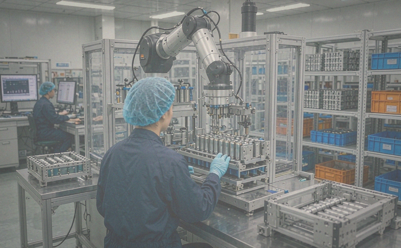
UFOPOWER supports common battery safety testing, transportation documentation, and market compliance requirements based on the selected battery configuration and target market. To begin an engineering evaluation, share the target voltage, capacity or energy, average power, continuous and peak current, available dimensions, operating temperature, target depth, charging method, communication requirements, development schedule, and estimated production volume. UFOPOWER can then evaluate the cell chemistry, series-parallel architecture, BMS, connector, thermal path, and mechanical pack structure as one integrated system.
What is the most important factor when choosing an AUV or ROV battery?
Cylindrical or pouch cells: which is better for underwater robots?
How do I estimate the energy my underwater robot battery needs?
Can a waterproof drone battery be used underwater?
What information should I provide for a custom underwater battery project?


 WhatsApp의
 EN
EN AR
AR DE
DE ES
ES FR
FR JP
JP KO
KO PT
PT RU
RU 홈 >
홈 >